Latex TikZ: A Step-by-Step Guide to Creating Professional Flow Charts
Category: Latex
Date: March 2023
Views: 2.06K
Greetings fellow latex lovers. In this article I will talk about creating flowcharts using LaTeX and TikZ. It's a useful skill to have, especially if you work in a technical field that involves presenting complex information in a visually appealing way.
When I first started creating flowcharts using TikZ, I found the process to be a bit daunting. However, with practice and a bit of patience, I was able to create flowcharts that not only looked professional but also effectively conveyed the information I wanted to present.
First define the shapes
To get started, you'll need to define the shapes and styles you want to use in your flowchart. In this code snippet, we define three styles: startstop, process, and decision. These styles will be used to define the shape, size, and color of the nodes in the flowchart like so:
\tikzstyle{process} = [rectangle, minimum width=3cm, minimum height=1cm, text centered, draw=black, fill=orange!30]
Once you've defined your styles, you can begin building your flowchart by defining the nodes and edges. Each node represents a step in the flowchart, and each edge represents the connection between those steps. In the code below, we define a series of nodes and edges to create a logical sequence of steps.
The following line will create a node named step2a that will be drawn below left of another node named decision1. And it will have the text "Step 2a". the y and x shifts will add more control over its placement.
\node[process, below left of=decision1, yshift=-1cm, xshift=5cm] (step2a) {Step 2a};
\documentclass{standalone}
\standaloneconfig{border=2mm 2mm 2mm 2mm}
\usepackage{tikz}

% Define the diamond shape
\usetikzlibrary{shapes.geometric}
\tikzset{diamond/.style={shape=diamond, draw, minimum size=1.5cm, text width=1.5cm, text centered, inner sep=0pt}}

% Define styles for the flowchart nodes
\tikzstyle{startstop} = [rectangle, rounded corners, minimum width=3cm, minimum height=1cm, text centered, draw=black, fill=red!30]
\tikzstyle{process} = [rectangle, minimum width=3cm, minimum height=1cm, text centered, draw=black, fill=orange!30]
\tikzstyle{decision} = [diamond, minimum width=3cm, minimum height=1cm, text centered, draw=black, fill=green!30]

\begin{document}

\begin{tikzpicture}[node distance=2cm, auto]
    % Define nodes
    \node (title) at (11.5,4) {\textbf{\Huge{My Flow Chart Title here}}};
    \node[startstop] (start) {Start};
    \node[process, right of=start, xshift=2cm] (step1) {Step 1};
    \node[decision, right of=step1, xshift=2cm] (decision1) {Decision 1};
    \node[process, below left of=decision1, yshift=-1cm, xshift=5cm] (step2a) {Step 2a};
    \node[process, above left of=decision1, yshift=1cm, xshift=5cm] (step2b) {Step 2b};
    \node[decision, left of=decision1, xshift=14cm] (decision2) {Decision 2};
    \node[process, below right of=decision2, yshift=-2cm, xshift=-4cm] (step3a) {Step 3a};
    \node[process, below left of=decision2, yshift=-2cm, xshift=4cm] (step3b) {Step 3b};
    \node[process, below right of=step3a, yshift=-1cm, xshift=1cm] (step4) {Step 4};
    \node[startstop, below of=step4] (end) {End};
    %% Define edges
    \draw[->] (start) -- (step1);
    \draw[->] (step1) -- (decision1);
    \draw[->] (decision1) -- node {yes} (step2a);
    \draw[->] (decision1) -- node {no} (step2b);
    \draw[->] (step2a) -- (decision2);
    \draw[->] (step2b) -- (decision2);
    \draw[->] (decision2) -- node {yes} (step3a);
    \draw[->] (decision2) -- node {no} (step3b);
    \draw[->] (step3a) -- (step4);
    \draw[->] (step3b) -- (step4);
    \draw[->] (step4) -- (end);
    %% Add dotted lines for clarity
    \draw[dotted] (step2a) -- (step2b);
    \draw[dotted] (step3a) -- (step3b);
\end{tikzpicture}

\end{document}
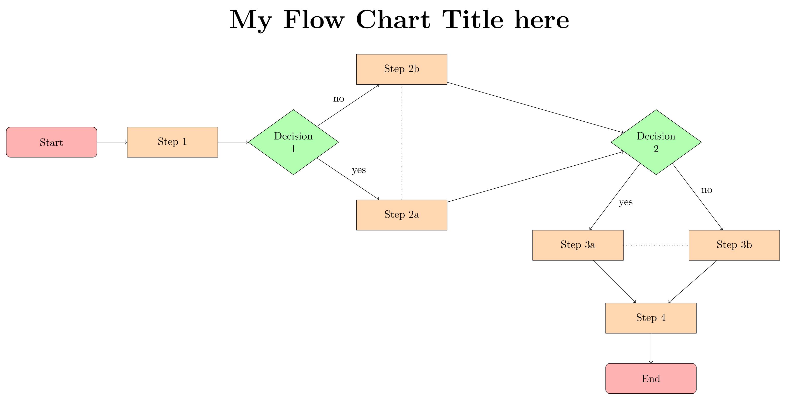
The above LaTeX code will create this flowchart:

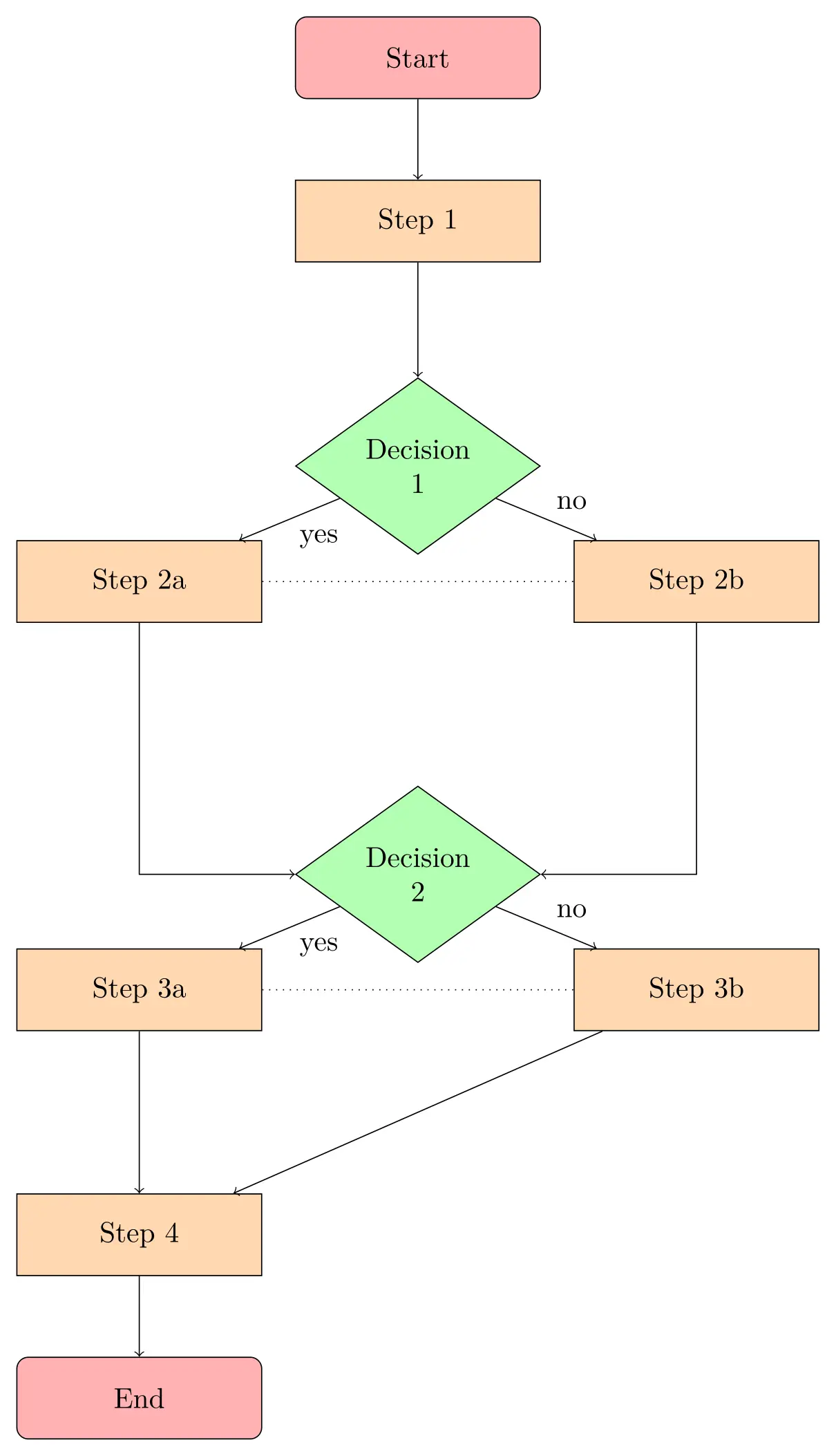
We can modify it to have a vertical layout:
\documentclass{standalone}
\standaloneconfig{border=2mm 2mm 2mm 2mm}
\usepackage{tikz}

% Define the diamond shape
\usetikzlibrary{shapes.geometric}
\tikzset{diamond/.style={shape=diamond, draw, minimum size=1.5cm, text width=1.5cm, text centered, inner sep=0pt}}

% Define styles for the flowchart nodes
\tikzstyle{startstop} = [rectangle, rounded corners, minimum width=3cm, minimum height=1cm, text centered, draw=black, fill=red!30]
\tikzstyle{process} = [rectangle, minimum width=3cm, minimum height=1cm, text centered, draw=black, fill=orange!30]
\tikzstyle{decision} = [diamond, minimum width=3cm, minimum height=1cm, text centered, draw=black, fill=green!30]

\begin{document}

\begin{tikzpicture}[node distance=2cm, auto]
    % Define nodes
    \node[startstop] (start) {Start};
    \node[process, below of=start] (step1) {Step 1};
    \node[decision, below of=step1, yshift=-1cm] (decision1) {Decision 1};
    \node[process, below left of=decision1, xshift=-2cm] (step2a) {Step 2a};
    \node[process, below right of=decision1, xshift=2cm] (step2b) {Step 2b};
    \node[decision, below of=decision1, yshift=-3cm] (decision2) {Decision 2};
    \node[process, below left of=decision2, xshift=-2cm] (step3a) {Step 3a};
    \node[process, below right of=decision2, xshift=2cm] (step3b) {Step 3b};
    \node[process, below of=step3a, yshift=-1cm] (step4) {Step 4};
    \node[startstop, below of=step4] (end) {End};
    % Define edges
    \draw[->] (start) -- (step1);
    \draw[->] (step1) -- (decision1);
    \draw[->] (decision1) -- node {yes} (step2a);
    \draw[->] (decision1) -- node {no} (step2b);
    \draw[->] (step2a) |- (decision2);
    \draw[->] (step2b) |- (decision2);
    \draw[->] (decision2) -- node {yes} (step3a);
    \draw[->] (decision2) -- node {no} (step3b);
    \draw[->] (step3a) -- (step4);
    \draw[->] (step3b) -- (step4);
    \draw[->] (step4) -- (end);
    % Add dotted lines for clarity
    \draw[dotted] (step2a) -- (step2b);
    \draw[dotted] (step3a) -- (step3b);
\end{tikzpicture}

\end{document}
One thing to keep in mind when creating your flowchart is to maintain a consistent style throughout. This includes keeping the size, shape, and color of your nodes and edges consistent, as well as keeping the text aligned and properly sized.
Overall, creating flowcharts using TikZ can seem intimidating at first, but with practice and a bit of creativity, you can create professional-looking flowcharts that effectively convey complex information. So, don't be afraid to dive in and experiment with different styles and layouts - who knows, you may even discover a new approach to flowcharting that sets you apart from the rest!
Related Articles


Most Recent Articles


Most Viewed Articles


0 Comments, latest